1.25G SFP Bi-di SM100GSB-20A
Catalogue index: 6971690793173
- Availability: Moderate ( 87 szt. )
- Delivery time: Implementation immediately
- Delivery: from PLN1.23 (Własny list przewozowy)
- Self pickup: free
Description
SM100GSB-20A Copper Small Form Pluggable
(SFP) transceivers are based on the SFP Multi Source Agreement (MSA).
They are compatible with the Gigabit Ethernet and 1000BASE-T standards
as specified in IEEE Std 802.3 . The 1000BASE-T physical layer IC (PHY)
can be accessed via I2C, allowing access to all PHY settings and features.
The 1000BASE-T uses the SFP's RX_LOS pin for link indication. If pull up
SFP's TX_DISABLE pin, PHY IC be reset..

Product choice
| Product part Number | Link Indicator on RX_LOS Pin | Support 1000base-X | Support SGMII |
| SFP-1000BASE-T | Yes | Yes(default) | Yes |
| SFP-1000BASE-T-SGMII | Yes | No | Yes |
SFP to Host Connector Pin Out
| Pin | Symbol | Name/Description | Ref |
| 1 | VEET | Transmitter Ground (Common with Receiver Ground) | 1 |
| 2 | TFAULT | Transmitter Fault. Not supported. |
|
| 3 | TDIS | Transmitter Disable. Laser output disabled on high or open. | 2 |
| 4 | MOD_DEF(2) | Module Definition 2. Data line for Serial ID. | 3 |
| 5 | MOD_DEF(1) | Module Definition 1. Clock line for Serial ID. | 3 |
| 6 | MOD_DEF(0) | Module Definition 0. Grounded within the module. | 3 |
| 7 | Rate Select | No connection required |
|
| 8 | LOS | Loss of Signal indication. Logic 0 indicates normal operation. | 4 |
| 9 | VEER | Receiver Ground (Common with Transmitter Ground) | 1 |
| 10 | VEER | Receiver Ground (Common with Transmitter Ground) | 1 |
| 11 | VEER | Receiver Ground (Common with Transmitter Ground) | 1 |
| 12 | RD- | Receiver Inverted DATA out. AC Coupled |
|
| 13 | RD+ | Receiver Non-inverted DATA out. AC Coupled |
|
| 14 | VEER | Receiver Ground (Common with Transmitter Ground) | 1 |
| 15 | VCCR | Receiver Power Supply |
|
| 16 | VCCT | Transmitter Power Supply |
|
| 17 | VEET | Transmitter Ground (Common with Receiver Ground) | 1 |
| 18 | TD+ | Transmitter Non-Inverted DATA in. AC Coupled. |
|
| 19 | TD- | Transmitter Inverted DATA in. AC Coupled. |
|
| 20 | VEET | Transmitter Ground (Common with Receiver Ground) | 1 |
Notes:
1. Circuit ground is connected to chassis ground
2. PHY disabled on TDIS > 2.0V or open, enabled on TDIS < 0.8V
3. Should be pulled up with 4.7k - 10k Ohms on host board to a voltage between 2.0 V and 3.6 V. MOD_DEF(0) pulls line low to indicate module is plugged in.
4. LVTTL compatible with a maximum voltage of 2.5V.
Not supported on 10/100/1000BASE-T.
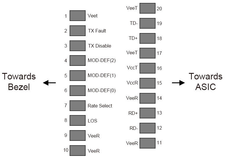
Diagram of host board connector block pin numbers and names
+3.3V Volt Electrical Power Interface
The SFP-1000BASE-T/SFP-1000BASE-T-SGMII has an input voltage range of 3.3 V +/- 5%. The 4V maximum voltage is not allowed for continuous operation.
| +3.3 Volt Electrical Power Interface | ||||||
| Parameter | Symbol | Min | Typ | Max | unit | Notes/Conditions |
| Supply Current | Is |
| 320 | 375 | mA | 1.2W max power over full range of voltage and temperature. See caution note below |
| Input Voltage | Vcc | 3.13 | 3.3 | 3.47 | V | Referenced to GND |
| Maximum Voltage | Vmax |
|
| 4 | V |
|
| Surge Current | Isurge |
|
| 30 | mA | Hot plug above steady state current. See caution note below |
| Caution: Power consumption and surge current are higher than the specified values in the SFP MSA. |
Low-Speed Signals
MOD_DEF(1) (SCL) and MOD_DEF(2) (SDA), are open drain CMOS signals (see section VII,
"Serial Communication Protocol"). Both MOD_DEF(1) and MOD_DEF(2) must be pulled up to host_Vcc.
| Low-Speed Signals, Electronic Characteristics | |||||
| Parameter | Symbol | Min | Max | unit | Notes/Conditions </td |